I've read several posts now about floating grounds. i haven't found a diagram of it.
i have a four connector rectifier:
dc +
dc -
ac
ac
and i have the lighting coil:
yellow wire to the normal wiring harness
questions:
where is the rectifier to be added? (please be specific)
is floating the ground simply removing the grounded side of the lighting circuit and connecting it to one of the ac leads on the rectifier, then the yellow ac wire to the other ac lead?
is the dc +/- just connected to the lights (with a fuse) or should it go through the regulator?
simple answers please, I'm not an electrician.
draw a picture if you like. simpler is better.
thanks
rectifier / floating ground ? (ac to dc howto)
-
ohgood
- Supporting Member II

- Posts: 925
- Joined: 10:00 am Jan 04 2014
- Country:
-
bufftester

- Platinum Member

- Posts: 3559
- Joined: 06:03 pm Oct 31 2012
- Country: USA
- Location: University Place, WA
- Been thanked: 10 times
- Contact:
Re: rectifier / floating ground ? (ac to dc howto)
See belowohgood wrote:questions:
where is the rectifier to be added? (please be specific)
Yesohgood wrote:is floating the ground simply removing the grounded side of the lighting circuit and connecting it to one of the ac leads on the rectifier, then the yellow ac wire to the other ac lead?
Yes. Normally a rectifier also has the regulator built in, you don't reuse the stock regulatorohgood wrote:is the dc +/- just connected to the lights (with a fuse) or should it go through the regulator?
Start hereohgood wrote:draw a picture if you like. simpler is better.
- KDX wiring1.jpg (51.12 KiB) Viewed 122805 times
- KDX wiring2.jpg (64.14 KiB) Viewed 122805 times
- KDX wiring3.jpg (41.69 KiB) Viewed 122805 times
- KDX wiring4.jpg (43.76 KiB) Viewed 122805 times
- KDX wiring5.jpg (62.02 KiB) Viewed 122805 times
Last edited by bufftester on 07:19 pm Jan 05 2020, edited 9 times in total.
-
koshari
- Member
- Posts: 54
- Joined: 04:02 am Jul 26 2011
- Country:
Re: rectifier / floating ground ? (ac to dc howto)
I suspect you would like to add a battery isolator so you dont drain and kill it.
The aus road versions low beams are on all the time if you use the standard switch. Auxilaries same consideration. The diode auctioneering in the bridge should prevent discharge back through the charging coil.
The aus road versions low beams are on all the time if you use the standard switch. Auxilaries same consideration. The diode auctioneering in the bridge should prevent discharge back through the charging coil.
-
ohgood
- Supporting Member II
- Posts: 925
- Joined: 10:00 am Jan 04 2014
- Country:
rectifier / floating ground ? (ac to dc howto)
wow ! i half expected a napkin sketch with all the same color of gray.
THAT however, IS AN AWESOME graphics representaion and instruction bufftestor !!
Thank you very much bufftestor and koshari !
I have ONE other question, after i viewed the excellent diagrams a few more times:
1) i've been running these LED's without a buffer / battery on the AC lighting circuit, and other than pulsing at lower rpms/idle, there hasn't been an issue yet. given my current use and results, no buffer/battery needed to continue with these lights, and possibly a cellphone charger on the soon to be new DC circuit ?
thanks, really. this is extremely helpful :)
-
ohgood
- Supporting Member II
- Posts: 925
- Joined: 10:00 am Jan 04 2014
- Country:
Re: rectifier / floating ground ? (ac to dc howto)
OK, i successfully removed the lighting coil ground, and installed a rectifier. i have AC input and DC voltage output from the rectifier. The two yellow taped leads are AC and the two bare leads are DC:

I've tried connecting the VR in line on the DC+ side, the DC- side, and the AC side, with no effect at all.
currently a have non regulated DC, that fluctuates from 30v at idle to 70-80v with a blip of the throttle.
what have i missed about regulating the voltage?
I've tried connecting the VR in line on the DC+ side, the DC- side, and the AC side, with no effect at all.
currently a have non regulated DC, that fluctuates from 30v at idle to 70-80v with a blip of the throttle.
what have i missed about regulating the voltage?
-
ohgood
- Supporting Member II
- Posts: 925
- Joined: 10:00 am Jan 04 2014
- Country:
rectifier / floating ground ? (ac to dc howto)
in the mean time, i'm gaining knowledge exponentially by watching youtube videos
-
koshari
- Member
- Posts: 54
- Joined: 04:02 am Jul 26 2011
- Country:
rectifier / floating ground ? (ac to dc howto)
goodi've been running these LED's without a buffer / battery on the AC lighting circuit, and other than pulsing at lower rpms/idle, there hasn't been an issue yet.
cant see why not if you have enough current.given my current use and results, no buffer/battery needed to continue with these lights, and possibly a cellphone charger on the soon to be new DC circuit ?
I've tried connecting the VR in line on the DC+ side, the DC- side, and the AC side, with no effect at all.
the factory regulator (2 wire) works by being placed across (or in parallel ) and breaks down at the regulation value (therefore stopping the voltage rising above this value) . series regulators are 3 wire and need an in/out/reference input.
thats what i would expect without a battery connected (if connected it would pull the higher voltage down as charge) , the bridge rectifier acts as a voltage pumper giving you effectively a dc voltage derived from the peak to peak from the ac side. i dont know if the standard regulator would work very well clamping the volts on the DC side if at all, a more efficient method may be a decent electrolytic cap and and povvo ebay dc/dc switching buck boost regulator,currently a have non regulated DC, that fluctuates from 30v at idle to 70-80v with a blip of the throttle.
http://www.ebay.com.au/itm/LM2577-Auto- ... 258bbbc311
what have i missed about regulating the voltage?
-
ohgood
- Supporting Member II
- Posts: 925
- Joined: 10:00 am Jan 04 2014
- Country:
Re: rectifier / floating ground ? (ac to dc howto)
hmm. I've exceeded my threshold for work on vs riding the bike again.
in going to put it back as it was and just ride instead.
if there isn't a plug and play solution instead of having to ask about each connection, wait on the internet to respond, then drag it all out again, I'm shelving the idea.
in going to put it back as it was and just ride instead.
if there isn't a plug and play solution instead of having to ask about each connection, wait on the internet to respond, then drag it all out again, I'm shelving the idea.
-
bufftester
- Platinum Member
- Posts: 3559
- Joined: 06:03 pm Oct 31 2012
- Country: USA
- Location: University Place, WA
- Been thanked: 10 times
- Contact:
Re: rectifier / floating ground ? (ac to dc howto)
Yyour rectifier does not have an integral regulator (it is an LTE5340 single phase diode bridge with no VR), so you would need to add one to the circuit by connecting to the DC output of your rectifier. Easier solution is to get one of the reg/rect units available instead. You don't need a battery if your current draw is low (as it is with LEDs). The battery is used to provide the high current source for your accessories. If you want to run without a battery, then don't bother converting to a DC system in the first place. The only benefit is if you need access to accessories (turn signals, horn, etc) for street legal reasons. The above pictures are really just the Baja Designs style conversion drawn out.
-
ohgood
- Supporting Member II
- Posts: 925
- Joined: 10:00 am Jan 04 2014
- Country:
Re: rectifier / floating ground ? (ac to dc howto)
the main reason was to be able to run a phone as a gps and have the ability to charge a friend's battery if his stator failed. i can always get one of those charging bricks to take care of the phone i guess.
-
koshari
- Member
- Posts: 54
- Joined: 04:02 am Jul 26 2011
- Country:
Re: rectifier / floating ground ? (ac to dc howto)
so why dont you just leave the AC part stock and run a bridge/cap/regulator solely for the phone, this way you only need to tap off the existing AC, bridge it to ac, place a cap in there to store a little of the Peak voltage and regulate it for the charger, in actual fact you could go straight to 5v (iam assuming your phone charges off 5v just like 95% of others do) using an adjustable regulator like this, http://www.ebay.com.au/itm/5-30V-to-0-8 ... 258ef04d0a
-
pumpguy
- Gold Member

- Posts: 840
- Joined: 10:00 am May 29 2012
- Country:
- Location: Spring Grove, Illinois
- Been thanked: 2 times
rectifier / floating ground ? (ac to dc howto)
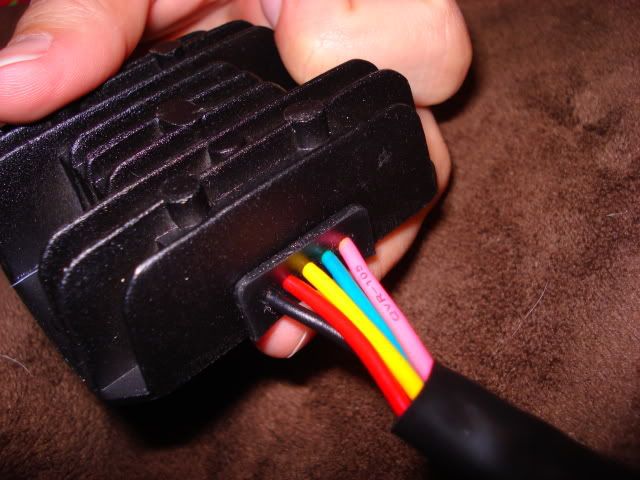
I was given a new regulator rectifier originally intended for a Chinese dirt bike of some sort. It has 5 wires; black, red, yellow, green, and pink.
I have been told to wire it as follows:
Black, 12VDC monitoring wire. (connect to 12vdc feed to brake light or headlight)
Red, Battery (DC charging system wire)
Yellow, Stator (AC charging system wire)
Green, Ground
Pink, Stator (AC charging system wire, typically white on the stator)
I understand these Chinese regulator rectifiers are quite inexpensive from various suppliers on the internet <outsidedistributing.com> , but I'm still confused about how to wire it up.
Do the above instructions make any sense, and is this regulator rectifier useable on an H series KDX with 85 watt lighting coil?
If yes, a diagram similar to those above would be greatly appreciated.
-
koshari
- Member
- Posts: 54
- Joined: 04:02 am Jul 26 2011
- Country:
Re: rectifier / floating ground ? (ac to dc howto)
Pumpy
is it the same as this?
i believe you would wire it like this, stressing if you have a ground in your AC supply (as is for the standard wiring) to keep the green (negative return) part as an isolated return path from the chassis.

is it the same as this?
Here is the wiring for a 5 wire rectifier. I bought mine from KS Power and got these details from Nick.
Left to right...
Black - 12VDC Monitoring wire (Connect to 12VDC feed to brake light or headlight)
Red - Battery (DC charging system wire)
Yellow - Stator (AC charging system wire)
Green - Ground
Pink - Stator (AC charging system wire, typically white on the stator)
Image
* Monitoring wire checks the 12VDC system and raises or lowers 12V output based on the needs of your system so your battery doesnt overcharge or undercharge. This wire does not need to be hooked up but is recommended.
Red wire goes directly to a constant 12v to charge the battery
i believe you would wire it like this, stressing if you have a ground in your AC supply (as is for the standard wiring) to keep the green (negative return) part as an isolated return path from the chassis.
-
bufftester
- Platinum Member
- Posts: 3559
- Joined: 06:03 pm Oct 31 2012
- Country: USA
- Location: University Place, WA
- Been thanked: 10 times
- Contact:
Re: rectifier / floating ground ? (ac to dc howto)
+1 What Koshari said, especially about the gounds. Once you go to a battery and float the ground you have to keep your lighting circuit isolated from the chassis. The updated 5 wire diagram would be:

-
koshari
- Member
- Posts: 54
- Joined: 04:02 am Jul 26 2011
- Country:
Re: rectifier / floating ground ? (ac to dc howto)
good work buffester.
i would imagine if you kept the ground at the magneto saving having to run another wire through the loom all would be good AS LONG AS YOU FLOAT THE DC RETURN.
i would imagine if you kept the ground at the magneto saving having to run another wire through the loom all would be good AS LONG AS YOU FLOAT THE DC RETURN.
-
pumpguy
- Gold Member
- Posts: 840
- Joined: 10:00 am May 29 2012
- Country:
- Location: Spring Grove, Illinois
- Been thanked: 2 times
rectifier / floating ground ? (ac to dc howto)
Koshari,
My reg/rec uses a similar 9 fin housing, unpainted aluminum. When viewed from the top as shown in your photo, from left to right, the color order of the leads is Black, Red, Pink, Yellow, Green.
Don't know if this makes any difference or not.
Markings on housing fin opposite leads outlet are: SHILE, WYQ 125
VOLTAGE REGULATOR
VOLTAGE: 12.8V
FO SHAN ELEC FACTORY
The box it came in is marked in 2 places. One side is marked with a bar code and the number 31600-FYS3-000 RECTIFIER.
The top of the box is marked FYM GENUINE PARTS. GUANGAHOU PANYU HUANAN MOTORS GROUP. This label is also marked with an email address FYMMOTOR@VIP.163.COM and a website URL www.hnmoto.com.
I sent off an email asking for a wiring diagram in English language, but what I did receive was all in Chinese characters. A second request produced the same result.
Additional searches all wanted brand name of vehicle it's used on, but I haven't a clue.
-
bufftester
- Platinum Member
- Posts: 3559
- Joined: 06:03 pm Oct 31 2012
- Country: USA
- Location: University Place, WA
- Been thanked: 10 times
- Contact:
Re: rectifier / floating ground ? (ac to dc howto)
True, you could just run the pink wire to a good frame ground, but as you said you have to make sure your DC system doesn't ground to the frame then. Saves you running an extra wire and pulling the flywheel/stator.koshari wrote:good work buffester.
i would imagine if you kept the ground at the magneto saving having to run another wire through the loom all would be good AS LONG AS YOU FLOAT THE DC RETURN.
-
koshari
- Member
- Posts: 54
- Joined: 04:02 am Jul 26 2011
- Country:
Re: rectifier / floating ground ? (ac to dc howto)
Well pumpy fortinately for me I have a road regesterable aussie model that comes standard with all dc Auxilaries, supplied rectifier/regulator and a 3 phase stator. But that dont help you of coarse.
To solve your dilemma it Might be time for a bit of bench testing. I take it you have a multimeter at least?
To solve your dilemma it Might be time for a bit of bench testing. I take it you have a multimeter at least?
-
LarsHudec
- Member
- Posts: 1
- Joined: 06:14 am Oct 01 2015
- Country:
Re: rectifier / floating ground ? (ac to dc howto)
For floating ground you must have to connect it to any neutral strip. It will work as a good floating ground. Connect your rectifier after the output of the alternator. For your lights you must use a regulator.
-
ohgood
- Supporting Member II
- Posts: 925
- Joined: 10:00 am Jan 04 2014
- Country:
rectifier / floating ground ? (ac to dc howto)
bought a new regulator/rectifier and connected head and tail/stop lights yesterday. I am not floating ground, since the lighting circuit (DC) is separate from the frame/ground/ac circuit.
keep in mind I've rewound the stator and deleted the stock regulator...
at idle, 8-9vdc, at just off 11-12vdc, ave any significant rev it drops back down to 8-9vdc.
I only have a 18w led headlight and 10w led taillight on the lighting , which are fed parallelparallel DC.
does it need more load to produce higher voltage ?
is there anything else to try to get decent DC voltage on this bike besides a battery?
frustrated again