Kawibunga wrote: 03:00 pm Feb 12 2025
Other plan is build a new shaft with the groove sized for a standard 106 oring, making sure it has the correct squeeze (about .010") for a dynamic application, as you're stretching it a bit.
So when you say the correct squeeze of around 0,010" compression, I assume you are referring to the cross-sectional compression, and not referencing the entire o.d of the o-ring be 0.010" larger than the i.d of the shaft bore? One way of reading that is double as much as the other! Thanks in advance for your clarification!
The well used worn out leaking seal measurements may also reflect dimensions of smaller o.d. than was original to this material due to age, heat, and being compressed for 20+ years, so if we know the amount of compression or squish intended, + the i.d. of the shaft bore in the cylinder, this might be a more accurate way to approach this.
This o-ring seems to fit the bill on everything if "8.05mm + .010" cross sectional squeeze" beyond the dimensions listed is what we're after:
https://www.theoringstore.com/store/ind ... ts_id=2937
and... that's considered a JIS standard size even!
1.5mm X 5.5mm V75 Fluorocarbon FKM O-Rings 75/80 Durometer Black (JIS S6-V75)
I should look through my o-ring kits, as 1 of the two is all JIS o-rings, like 500 of them! The other is all exclusively metric as well, but not the standardized JIS Japanese Industrial Standards sizing. This would be 8.50mm o.d. vs your drawing of the old seal (shrunken with age????) at 8.05mm, assuming your 0.010"/0.254mm squish factor added to the cross sectional dimension (this could be a total misinterpretation or your intent though, perhaps 8.05mm was your final dimension prior to squish but after considering aging and permanent compression of the existing old packing seal).
The other issue is, the cross section being a round o-ring and not a rectangular dimension x-ring, we would have extra space next to it...
Having the groove machined slightly deeper would of course be best for the seal fitment, as then we could just use a larger o-ring cross section that fits the width of the groove. *OR*... since cutting the groove deeper would weaken the shaft technically, perhaps we cut the groove wider instead, and run two of these o-rings side by side? That right there sounds like a very viable option to me and is a simple mod with no reduction in the structural soundness of the shaft (if it ever even was close to it's maximum allowable forces working against it in the first place...)
Assuming the above added .010" sectional squish above the 8.05mm o.d. worn in dimension, this first ring applies, but if 8.03mm total uncompressed o.d. is what we're after, the second is a great candidate:
Metric X-Ring:
https://www.oringsandmore.com/x-rings-5 ... um-10-pcs/
X Rings 5.28 x 1.78mm Minimum 10 pcs
$0.05
That's a bit more required compression than 0.254mm as stated (0.010"), assuming that was cross sectional compression, and not total diameter compression.
if machining the shaft groove down in diameter/depth slightly, this one comes out to listed dimension of 8.03mm o.d., whereas your drawing shows 8.05mm as the actual size of the (well used worn out?) original
https://www.oringsandmore.com/x-rings-4 ... um-10-pcs/
X Rings 4.47 x 1.78mm Minimum 10 pcs
4.47 ID x 1.78 CS X Ring X Rings
$0.05
EDIT - this size converted to decimal inch sizing equates to exactly the standard "-008" SAE size.
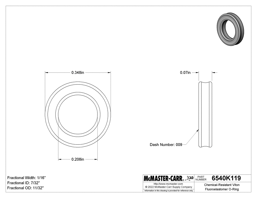
Or this perhaps, inch side, but perhaps it would stretch and compress? The closest "SAE" sizes I can find in any format o-ring x-ring etc are all seeming to be listed as size standard "-009" - although you mentioning a dash 008 makes me think the 8.05mm dimension you list was total and not with .010" / .254mm sectional squish added.
https://www.mcmaster.com/6540K119/
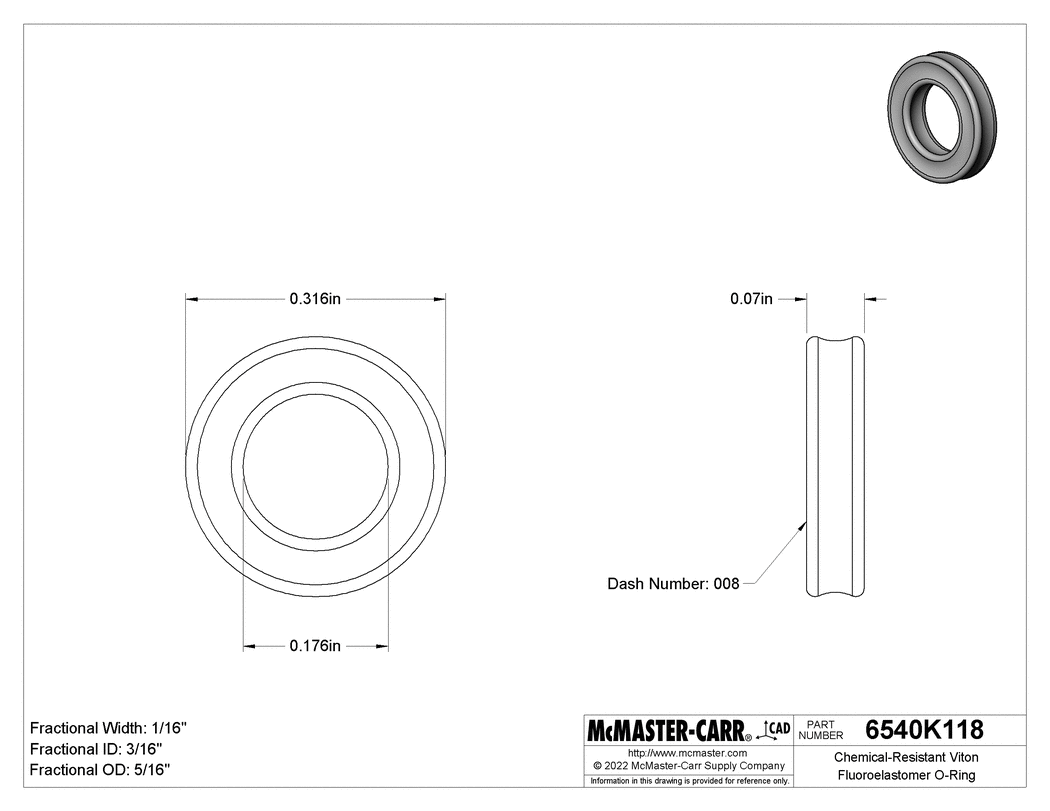
 *OR* your -008 size in an x-ring, these are both Viton Fluoroelastomer x-rings, a much better choice for an engine cylinder:
 McMaster-Carr -008 X-ring Viton 6540K118 https://www.mcmaster.com/6540K118/
Lastly, if a fatter o-ring or x-ring could not be sourced to fill the width of the shaft groove, why not leave the depth alone and modify the width slightly to fit TWO o-rings of the actual cross sectional requirement or close?
I think the friction and compression / squish fit is critical, as we know our KIPS actuator pins can be dislodged with force from their pressed in fitment onto the shaft engaging the KIPS governor timer assembly, so we don't want to introduce too much resistance in this assembly, so the installed o.d. is a sensitive area to get just right, just enough to seal but not add significant resistance. I may zap my KIPS pin with a MIG welder as a precautionary measure anyways, but more force required will still wear down all components involved more readily, which we do not want...