Posted: 02:23 pm Feb 20 2011
I'm eagerly awaiting the new test data!
Discussion group for KDX enthusiasts
https://kdxrider.net/forums/
Exactly !chkdx wrote:Well, I actually am an electrical engineer, so I thought I'd throw a thought in here. Nick, your first test was in fact incorrect. You measured open circuit voltage and short circuit current separately, so they cannot be multiplied together to obtain the correct wattage. You do, indeed, have to measure them simultaneously to get the real wattage.
Think of it like a fuel pump. If you measure the pump's output pressure with the outlet blocked by the pressure gage, the reading will be the max pressure the pump can put out. If you then check the flow by just running the pump output into a bucket, the pump is putting up plenty of flow, but no pressure, so it's incorrect to say "This pump puts out 30 gallons per hour at 15 PSI" when the pump's max pressure was 15 PSI.
Now you brought up the regulator. Let's add a pressure regulator to the fuel pump, and set it at 12.5 PSI (kinda like the 12.5 volts of a voltage regulator). If you then run the output of the regulator into a bucket, the output pressure is still zero, not 12.5 PSI, so it's still not a valid test. What you have to do is restrict the outlet flow (with, say a valve) until the pressure before the valve just barely drops just below 12.5 PSI, say to 12 PSI then measure the flow out of the valve. You can then say "This pump flows X gallons per hour at 12 PSI."
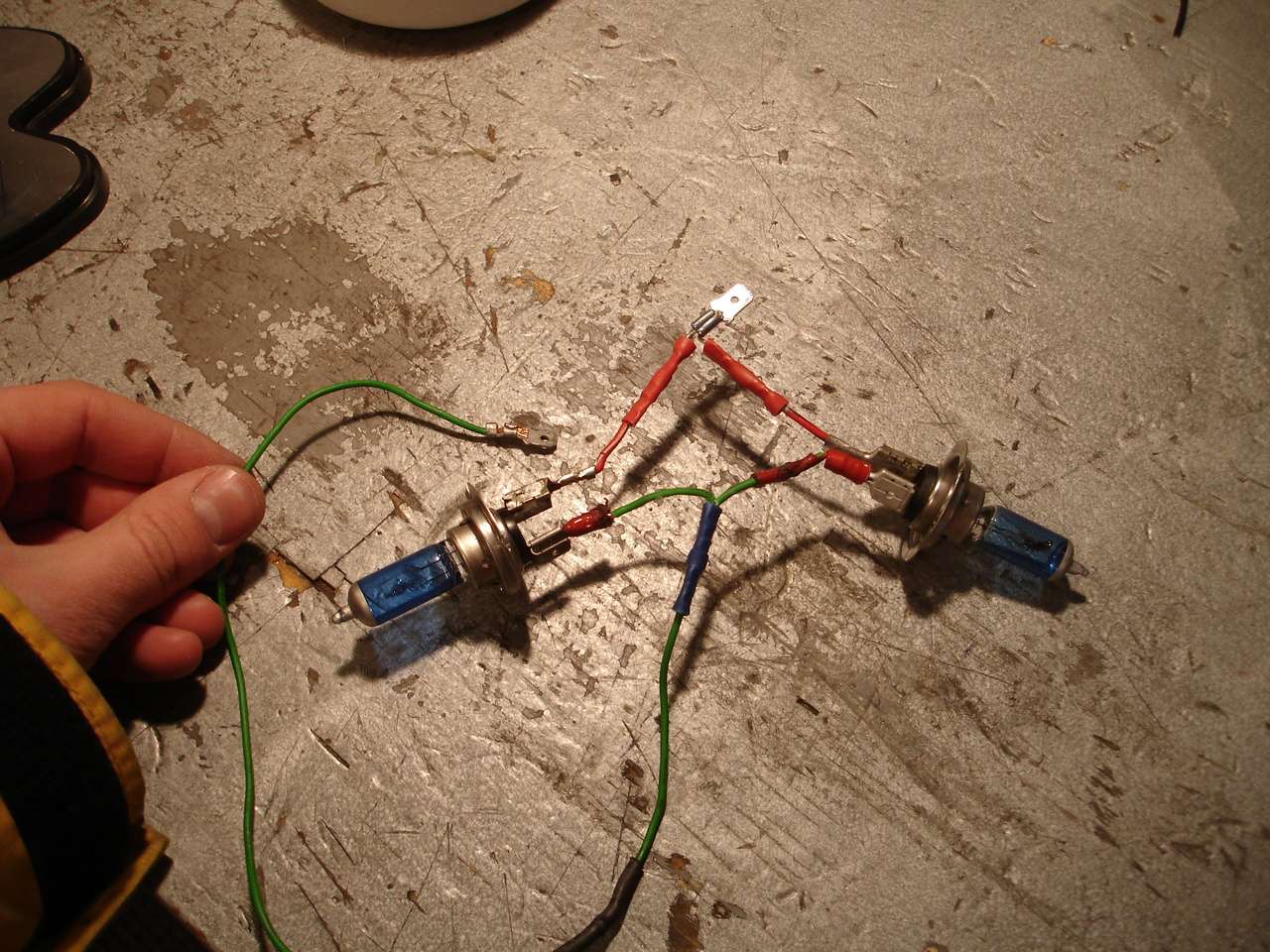
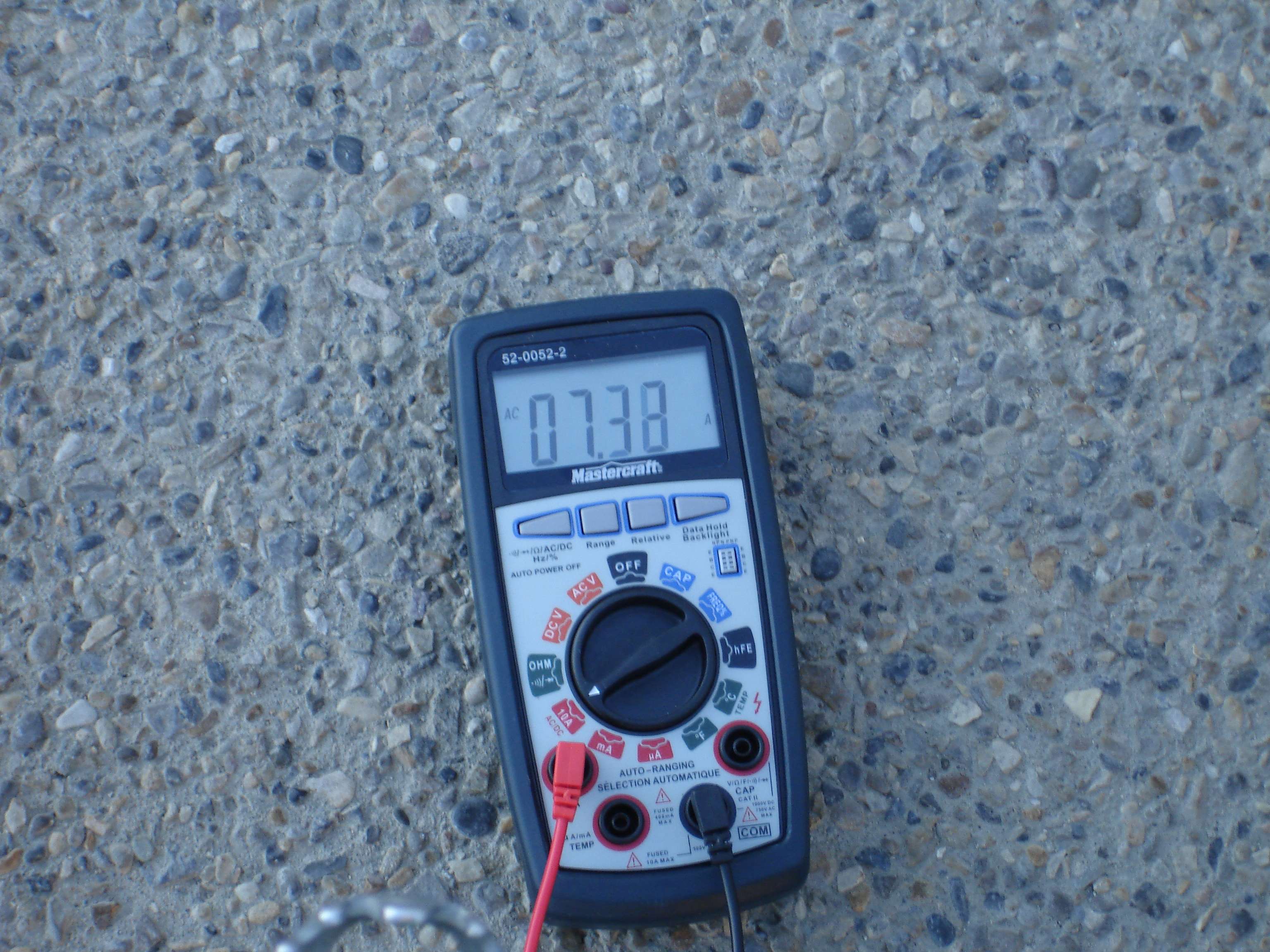
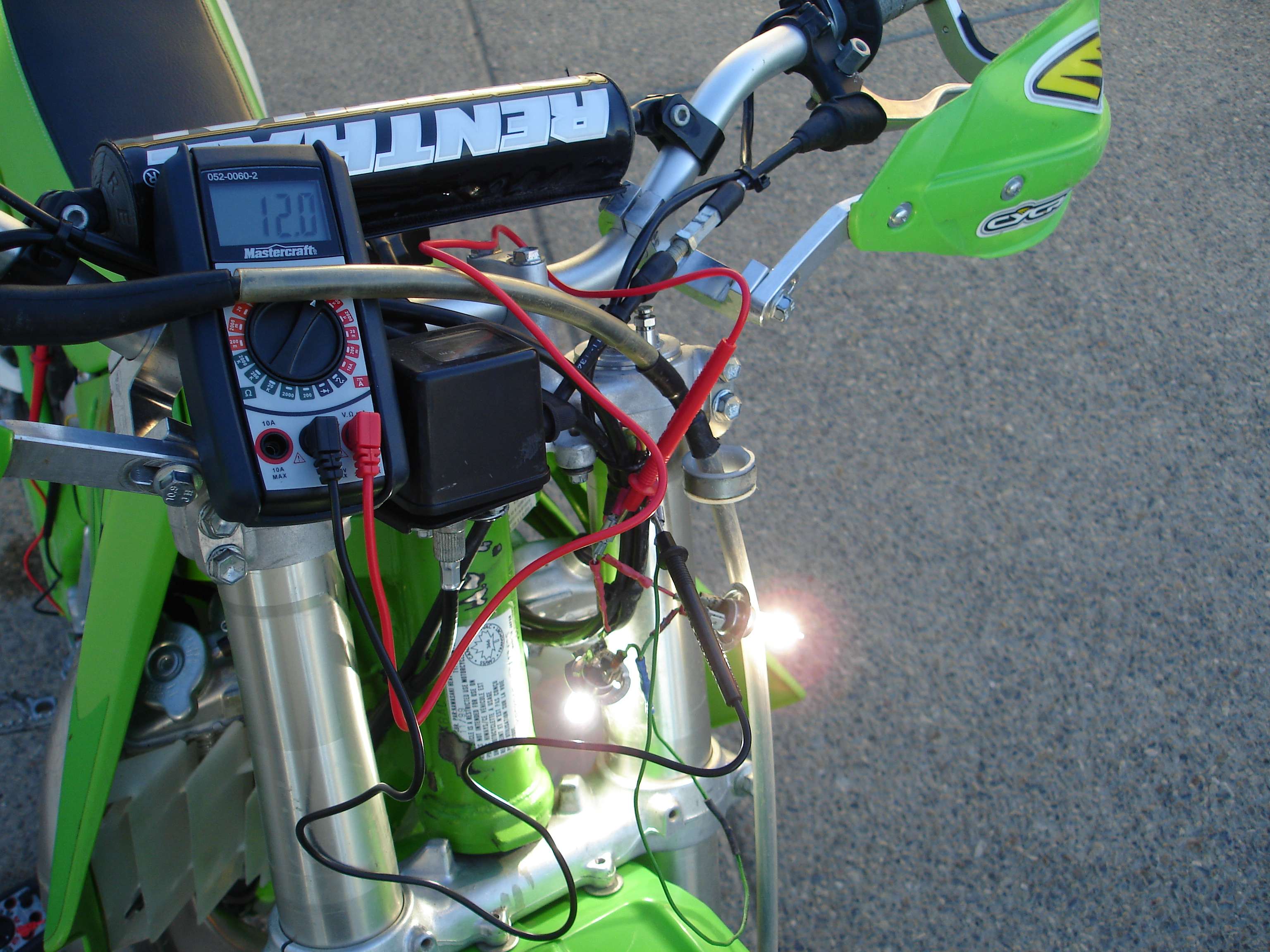
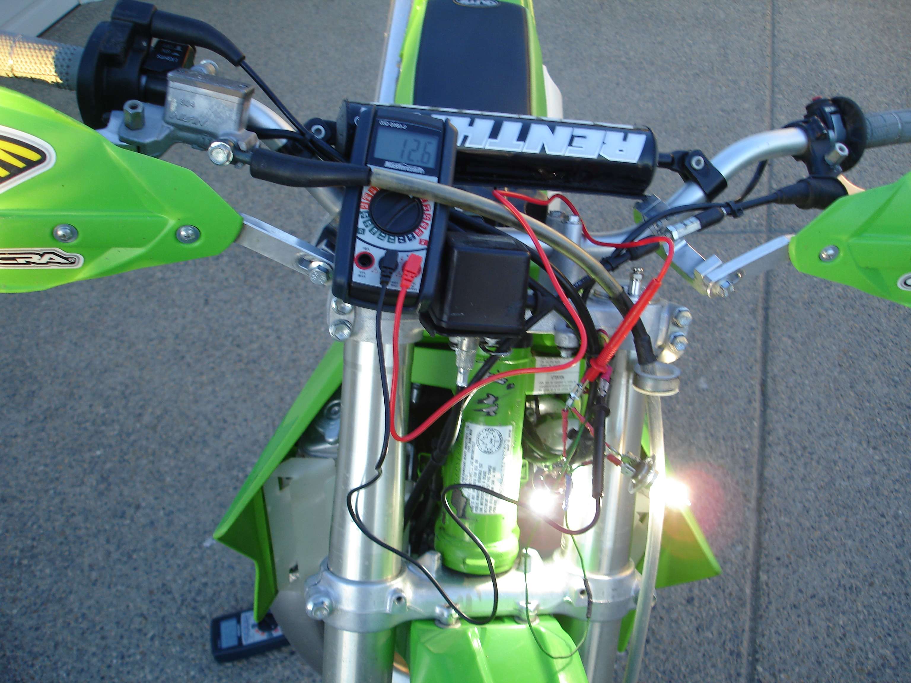
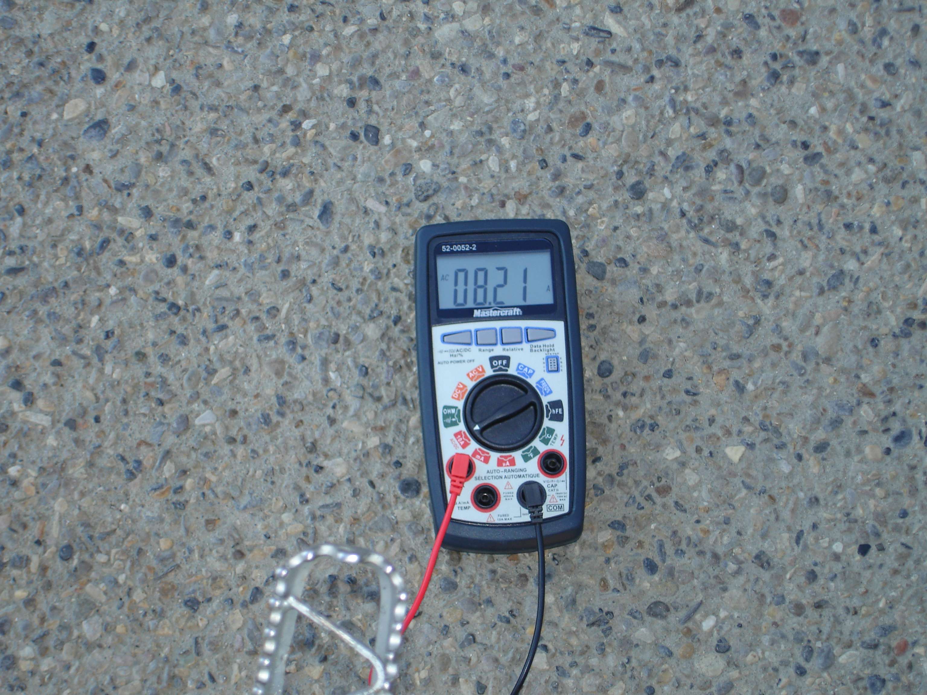
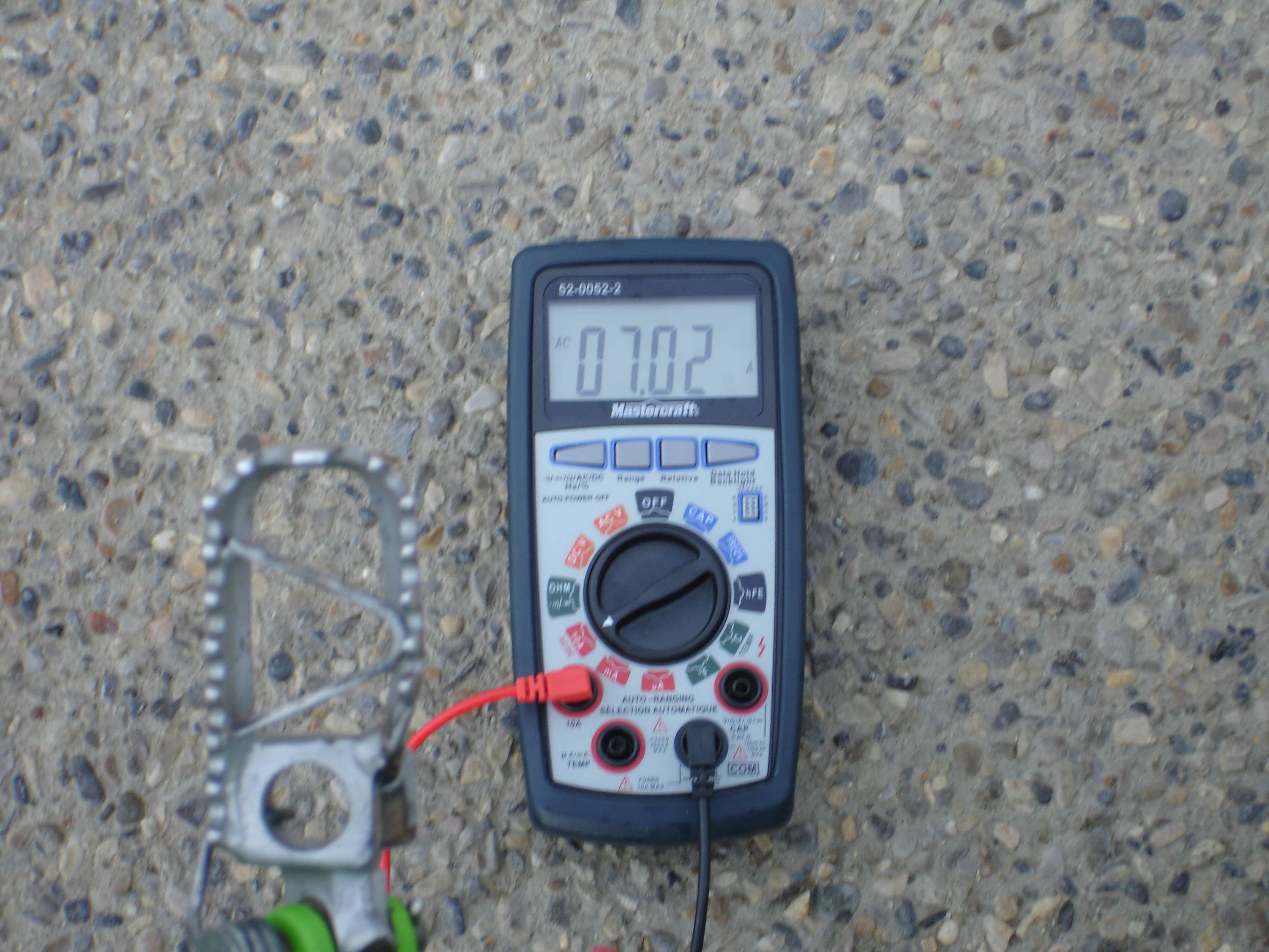
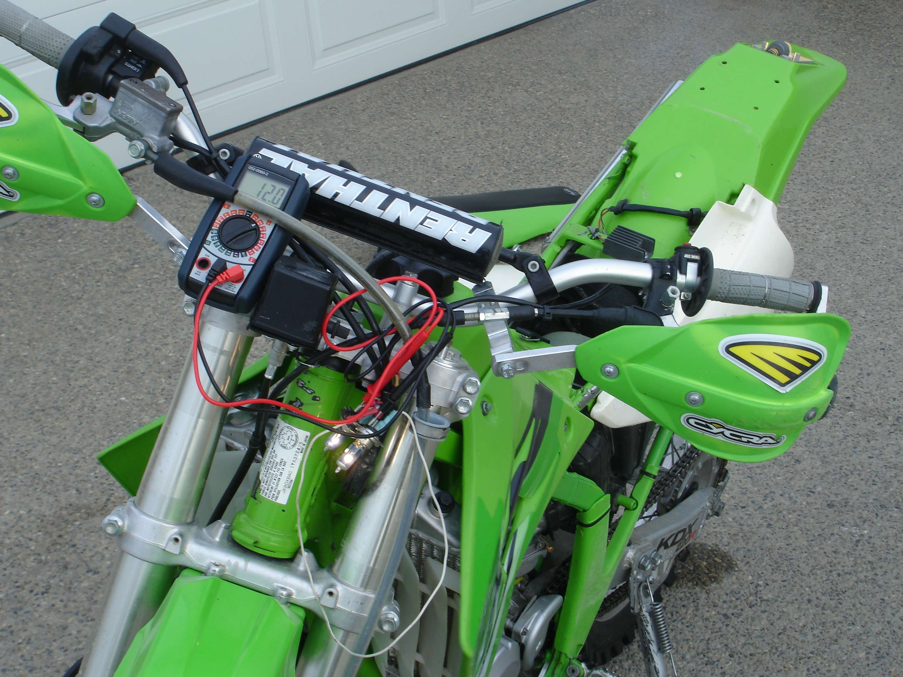
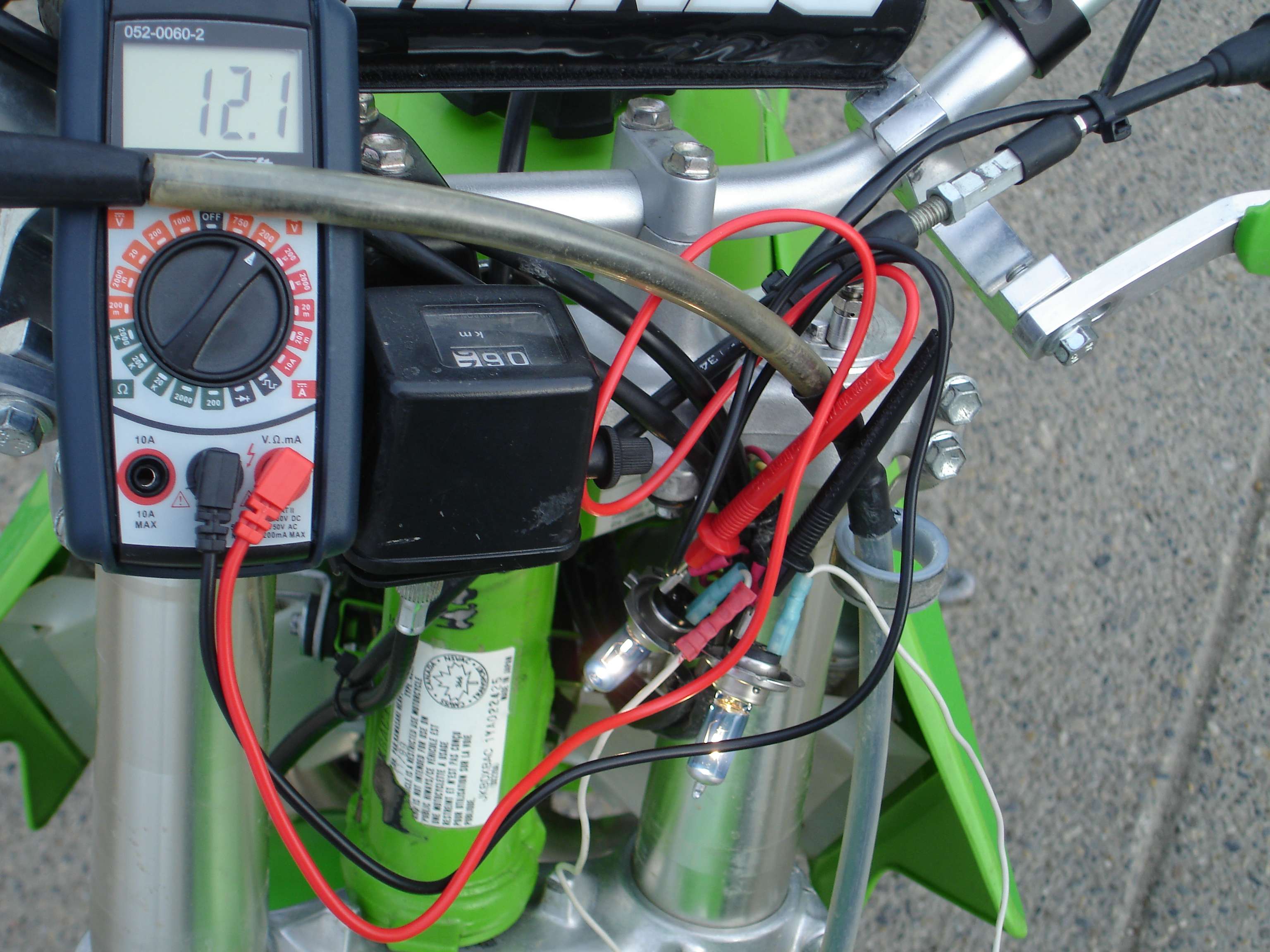
Similarly, the right way to do your electrical test is to restrict the current flow through the ammeter, with resistors or extra bulbs, until the voltage seen by those resistors or bulbs is, say, 12 Volts, then note the amperage. You can then say "The output is X amps at 12 volts, therefore the wattage is X amps times 12 volts." Note: the resistors or bulbs are put in series with the ammeter for this test.
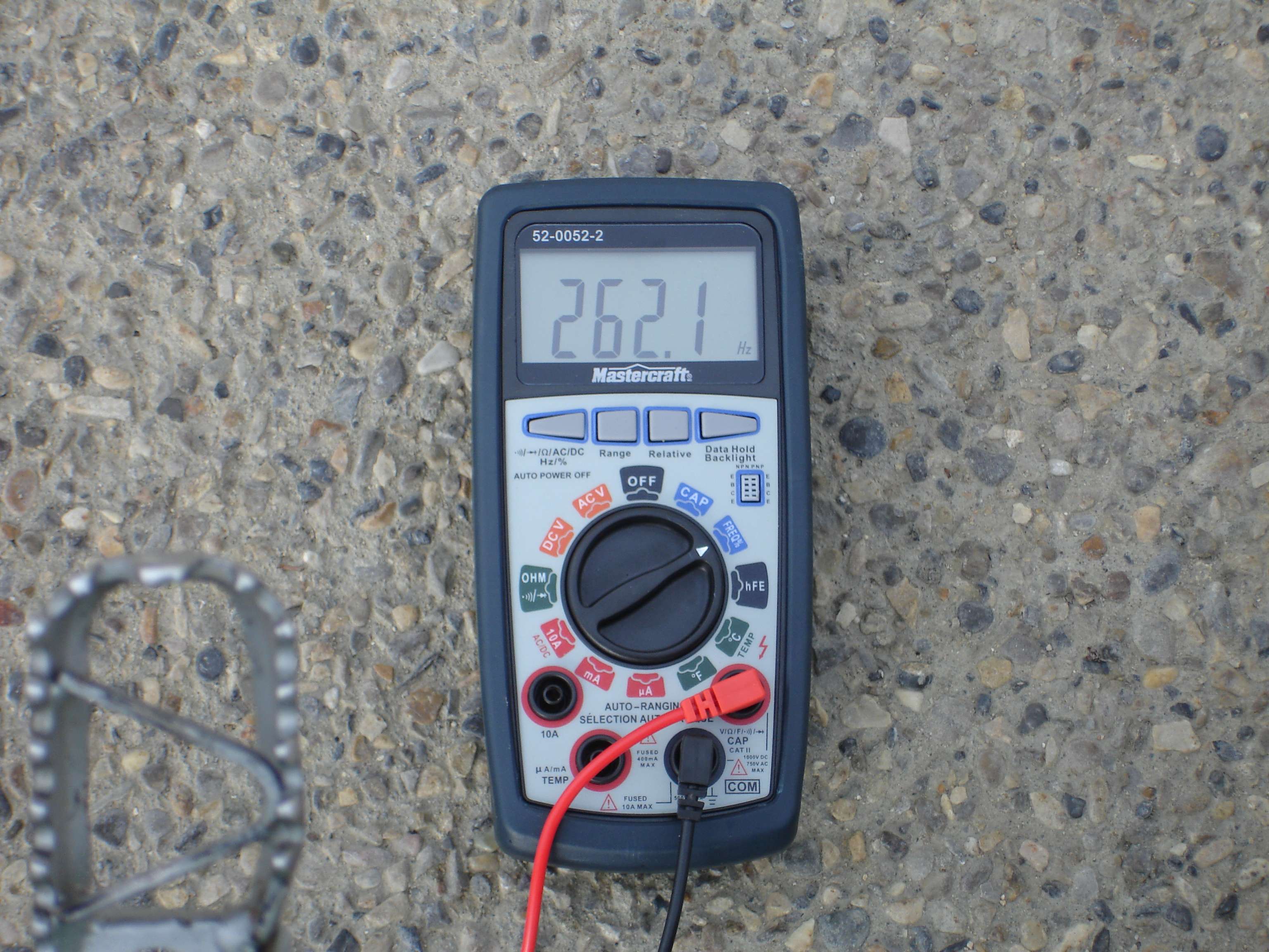
You are correct that trying to measure output at much above 12 volts won't work as the regulator will shunt current to ground to maintain around 12.5 volts. However, you may well find (probably WILL find) that if you rev the engine up to say 5000 rpm during the test, you'll have to reduce the test resistance to keep the voltage at 12 Volts, so more current will flow, and available wattage will therefore be increased at higher rpm.
Clear as mud? Hope it helps! I'll be watching this closely as I'm going to try rewinding my stator as well.

Slick_Nick wrote:In series to the amp meter? They are in series with the amp meter. Why do the bulbs need to be wired in paralell?
rbates9 wrote:I think that the point the OP was making was that you can make your own for cheap that puts out more power than stock. I think he did a great job showing everyone what to do and how to do it. Getting down to splitting watts don't really matter. If you want one that has a certified rating go buy one.